STAINLESS STEEL BALL VALVES
Stainless steel ball valves in ASTM A351-CF8M (1.4408), with PTFE seats and blow-out proof stems. Available in two-piece and three-piece versions – threaded or weldable – as well as versions with an ISO 5211 mounting pad for a pneumatic actuator, in sizes from DN8 (1/4″) to DN100 (4″). Click “Details” under each valve for technical drawings, materials and dimension tables.

TWO-PIECE, THREADED
Features
- Threads according to ASME B1.20.1 (NPT), DIN 2999 and BS 21, ISO 228/1 and ISO 7/1
- Investment casting
- Blow-out proof stem
- PTFE seat
- Working pressure: 1/4″–1″ 2000 W.O.G., 1-1/4″–2″ 1500 W.O.G., 2-1/2″–4″ 1000 W.O.G.
Details – technical data
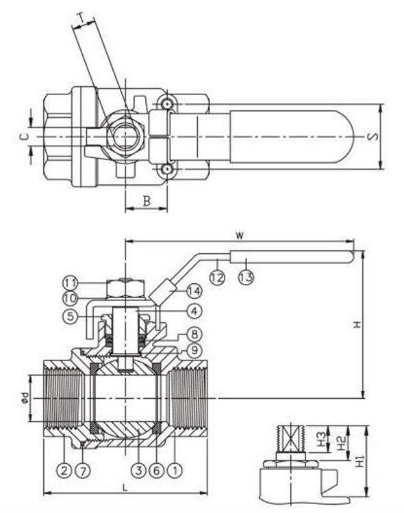
Standard
| Applicable standard | |
|---|---|
| Test and inspection | API 598 |
Materials
| Item | Part | Material | |
|---|---|---|---|
| 1 | Body | ASTM A351-CF8M / 1.4408 | ASTM A216-WCB / 1.0619 |
| 2 | Cap | ||
| 3 | Ball | ASTM A351-CF8M | |
| 4 | Stem | ASTM A276-316 | |
| 5 | Gland nut | AISI 304 | |
| 6 | Ball seal | PTFE / RTFE | |
| 7 | Body seal | PTFE | |
| 8 | Stem packing | PTFE / RTFE | |
| 9 | Thrust washer | PTFE | |
| 10 | Spring washer | AISI 304 | |
| 11 | Nut | ||
| 12 | Handle | ||
| 13 | Handle sleeve | PVC | |
| 14 | Locking device | AISI 304 | |
Pressure / temperature diagram
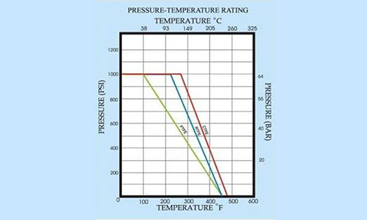
Dimensions – metric (mm)
| Pressure | DN | d | L | H | W | S | B | C |
|---|---|---|---|---|---|---|---|---|
| PN 150 | 8 | 12 | 60,5 | 50 | 102 | 28 | 14 | 5 |
| 10 | 13 | 60,5 | 50 | 102 | 28 | 14 | 5 | |
| 15 | 15 | 64 | 50 | 102 | 28 | 14 | 5 | |
| 20 | 20 | 77 | 62 | 120 | 35 | 22 | 6,5 | |
| 25 | 25 | 90 | 75,5 | 159 | 35 | 22 | 8 | |
| PN 100 | 32 | 32 | 100 | 81 | 159 | 38 | 24 | 8 |
| 40 | 38 | 118 | 98 | 188 | 38 | 24 | 9 | |
| 50 | 50 | 138 | 108 | 188 | 38 | 24 | 9 | |
| PN 63 | 65 | 65 | 166,5 | 136 | 245 | 55 | 35 | 12 |
| 80 | 80 | 193 | 147 | 245 | 55 | 35 | 12 | |
| 100 | 100 | 260 | 183 | 320 | 60 | 50 | 16 |
| Pressure | DN | H1 | H2 | H3 | T | Torque (Nm) | Weight (kg) |
|---|---|---|---|---|---|---|---|
| PN 150 | 8 | 32,5 | 12,5 | 10,5 | 5/16″W | 4,07 | 0,26 |
| 10 | 32,5 | 12,5 | 10,5 | 5/16″W | 4,07 | 0,28 | |
| 15 | 32,5 | 12,5 | 10,5 | 5/16″W | 4,41 | 0,3 | |
| 20 | 40,5 | 16 | 13,5 | 3/8″W | 5,88 | 0,55 | |
| 25 | 50 | 18 | 15,5 | 7/16″W | 7,35 | 0,84 | |
| PN 100 | 32 | 49 | 17 | 15,5 | 7/16″W | 8,82 | 1,26 |
| 40 | 60 | 19 | 17,5 | 1/2″W | 13,2 | 2 | |
| 50 | 62 | 20 | 17,5 | 1/2″W | 16,2 | 3,13 | |
| PN 63 | 65 | 79 | 31 | 30,5 | 3/4″W | 44,1 | 6 |
| 80 | 78,5 | 31 | 30,5 | 3/4″W | 46,6 | 10,1 | |
| 100 | 99 | 53 | 42 | 1″W | – | – |
Dimensions – imperial (in)
| Pressure | NPS | d | L | H | W | S | B | C |
|---|---|---|---|---|---|---|---|---|
| 2000 W.O.G. | 1/4″ | 0,47 | 2,38 | 1,97 | 4,02 | 1,1 | 0,55 | 0,2 |
| 3/8″ | 0,51 | 2,38 | 1,97 | 4,02 | 1,1 | 0,55 | 0,2 | |
| 1/2″ | 0,59 | 2,52 | 1,97 | 4,02 | 1,1 | 0,55 | 0,2 | |
| 3/4″ | 0,79 | 3,03 | 2,44 | 4,72 | 1,38 | 0,87 | 0,26 | |
| 1″ | 0,98 | 3,54 | 2,97 | 6,26 | 1,38 | 0,87 | 0,31 | |
| 1500 W.O.G. | 1-1/4″ | 1,26 | 3,94 | 3,19 | 6,26 | 1,5 | 0,94 | 0,31 |
| 1-1/2″ | 1,5 | 4,65 | 3,86 | 7,4 | 1,5 | 0,94 | 0,35 | |
| 2″ | 1,97 | 5,43 | 4,25 | 7,4 | 1,5 | 0,94 | 0,35 | |
| 1000 W.O.G. | 2-1/2″ | 2,56 | 6,56 | 5,35 | 9,65 | 2,17 | 1,38 | 0,47 |
| 3″ | 3,15 | 7,6 | 5,79 | 9,65 | 2,17 | 1,38 | 0,47 | |
| 4″ | 3,94 | 10,24 | 7,2 | 12,6 | 2,36 | 1,97 | 0,63 |
| Pressure | NPS | H1 | H2 | H3 | T | Torque (in-lb) | Weight (lb) |
|---|---|---|---|---|---|---|---|
| 2000 W.O.G. | 1/4″ | 1,28 | 0,49 | 0,41 | 5/16″W | 36,02 | 0,57 |
| 3/8″ | 1,28 | 0,49 | 0,41 | 5/16″W | 36,02 | 0,62 | |
| 1/2″ | 1,28 | 0,49 | 0,41 | 5/16″W | 39,03 | 0,66 | |
| 3/4″ | 1,59 | 0,63 | 0,53 | 3/8″W | 52,04 | 1,21 | |
| 1″ | 1,97 | 0,71 | 0,61 | 7/16″W | 65,05 | 1,85 | |
| 1500 W.O.G. | 1-1/4″ | 1,93 | 0,67 | 0,61 | 7/16″W | 78,06 | 2,78 |
| 1-1/2″ | 2,36 | 0,75 | 0,69 | 1/2″W | 116,83 | 4,41 | |
| 2″ | 2,44 | 0,79 | 0,69 | 1/2″W | 143,38 | 6,9 | |
| 1000 W.O.G. | 2-1/2″ | 3,11 | 1,22 | 1,2 | 3/4″W | 390,32 | 13,23 |
| 3″ | 3,09 | 1,22 | 1,2 | 3/4″W | 412,44 | 22,27 | |
| 4″ | 3,9 | 2,09 | 1,65 | 1″W | – | – |

TWO-PIECE WITH PNEUMATIC ACTUATOR MOUNTING PAD
Features
- Threads according to ASME B1.20.1 (NPT), DIN 2999 and BS 21, ISO 228/1 and ISO 7/1
- Spring system on stem
- Fixed spring load
- Blow-out proof stem
- PTFE seat
- ISO 5211 direct mounting pad for the actuator
- Locking device
- Anti-static device
Details – technical data
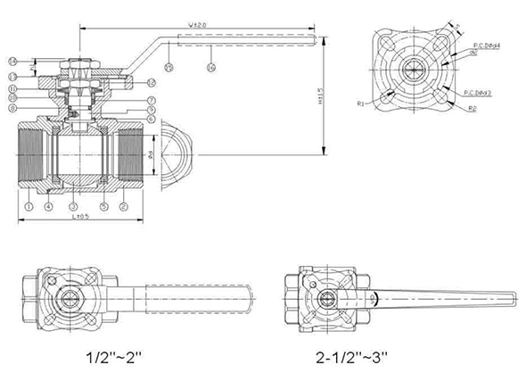
Standard
| Applicable standard | |
|---|---|
| Test and inspection | API 598 |
Materials
| Item | Part | Material |
|---|---|---|
| 1 | Cap | ASTM A351-CF8M / 1.4408 |
| 2 | Body | |
| 3 | Ball | |
| 4 | Body seal | PTFE |
| 5 | Ball seat | PTFE / RTFE |
| 6 | Thrust washer | PTFE |
| 7 | Stem packing | |
| 8 | O-ring | VITON |
| 9 | Stem | ASTM A276-316 |
| 10 | Gland ring | AISI 304 |
| 11 | Belleville washer | |
| 12 | Lock washer | |
| 13 | Lock pad | |
| 14 | Stem nut | |
| 15 | Handle | |
| 16 | Handle sleeve | PVC |
Pressure / temperature diagram
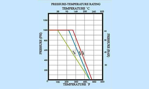
Dimensions – metric (mm)
| Pressure | DN | d | L | H | W | S | h1 | d2 | d3 | d4 | R1 | R2 | Torque (Nm) |
|---|---|---|---|---|---|---|---|---|---|---|---|---|---|
| PN 63 | 15 | 15 | 58 | 63 | 120 | 9 | 8 | 31 | 36 | 42 | 2,75 | 2,75 | 5,5 |
| 20 | 20 | 65,6 | 69 | 9 | 7,5 | ||||||||
| 25 | 25 | 78,7 | 76 | 148 | 11 | 10 | 35,5 | 42 | 50 | 2,75 | 3,5 | 11 | |
| 32 | 32 | 90 | 82 | 15 | |||||||||
| 40 | 38 | 105 | 99 | 178 | 14 | 14 | 56 | 50 | 70 | 3,5 | 4,5 | 20 | |
| 50 | 50 | 124 | 108 | 40 | |||||||||
| 65 | 63 | 146,2 | 123 | 325 | 17 | 20,5 | 76 | 70 | 102 | 4,5 | 5,5 | 60 | |
| 80 | 76 | 163,7 | 131,5 | 85 |
Dimensions – imperial (in)
| Pressure | NPS | d | L | H | W | S | h1 | d2 | d3 | d4 | R1 | R2 | Torque (in-lb) |
|---|---|---|---|---|---|---|---|---|---|---|---|---|---|
| 1000 W.O.G. | 1/2″ | 0,59 | 2,28 | 2,48 | 4,72 | 0,35 | 0,31 | 1,22 | 1,42 | 1,65 | 0,11 | 0,11 | 48,68 |
| 3/4″ | 0,79 | 2,58 | 2,72 | 0,35 | 66,38 | ||||||||
| 1″ | 0,98 | 3,1 | 2,99 | 5,83 | 0,43 | 0,39 | 1,4 | 1,65 | 1,97 | 0,11 | 0,14 | 97,36 | |
| 1-1/4″ | 1,26 | 3,54 | 3,23 | 132,76 | |||||||||
| 1-1/2″ | 1,5 | 4,13 | 3,9 | 7,01 | 0,55 | 0,55 | 2,2 | 1,97 | 2,76 | 0,14 | 0,18 | 177,01 | |
| 2″ | 1,97 | 4,88 | 4,25 | 354,03 | |||||||||
| 2-1/2″ | 2,5 | 5,76 | 4,8 | 12,08 | 0,67 | 0,81 | 3 | 2,76 | 4,02 | 0,18 | 0,22 | 531,04 | |
| 3″ | 2,99 | 6,44 | 5,18 | 752,31 |

THREE-PIECE, THREADED
Features
- Threads according to ASME B1.20.1 (NPT), DIN 2999 and BS 21, ISO 228/1 and ISO 7/1
- Investment casting
- Blow-out proof stem
- PTFE seat
Details – technical data
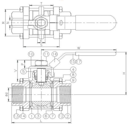
Standard
| Applicable standard | |
|---|---|
| Test and inspection | API 598 |
Materials
| Item | Part | Material | |
|---|---|---|---|
| 1 | Body | ASTM A351-CF8M / 1.4408 | ASTM A216-WCB / 1.0619 |
| 2 | Cap | ||
| 3 | Ball | ASTM A351-CF8M / 1.4408 | |
| 4 | Stem | ASTM A276-316 | |
| 5 | Gland nut | AISI 304 | |
| 6 | Ball seat | PTFE / RTFE/CTFE | |
| 7 | Body seal | PTFE | |
| 8 | Stem packing | ||
| 9 | Thrust washer | ||
| 10 | Spring washer | AISI 304 | |
| 11 | Stem nut | ASTM A194 GR.8 | |
| 12 | Screw | ASTM A193-B8 | |
| 13 | Bolt nut | ||
| 14 | Spring washer | AISI 304 | |
| 15 | Handle | ASTM A167-304 | |
| 16 | Locking device | ||
| 17 | Handle sleeve | PVC | |
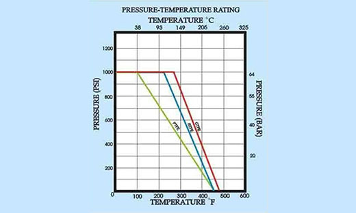
Pressure / temperature diagram
Dimensions – metric (mm)
| Pressure | DN | d | L | H | W | S | T |
|---|---|---|---|---|---|---|---|
| PN 63 | 8 | 11,6 | 64,5 | 54 | 102 | 35,5 | 21,5 |
| 10 | 12,7 | 64,5 | 54 | 102 | 35,5 | 21,5 | |
| 15 | 15 | 66 | 57 | 102 | 38 | 24 | |
| 20 | 20 | 83,5 | 66 | 120,5 | 43 | 28 | |
| 25 | 25 | 95 | 76 | 158,5 | 54 | 35 | |
| 32 | 32 | 111,2 | 81 | 158,5 | 65 | 45 | |
| 40 | 38 | 129,8 | 98 | 188 | 75 | 55 | |
| 50 | 50 | 151 | 106 | 188 | 88 | 66 | |
| 65 | 65 | 184 | 138 | 245 | 114 | 86 | |
| 80 | 80 | 209 | 154 | 245 | 132 | 100 | |
| 100 | 100 | 234,4 | 178 | 320 | 158 | 125 |
| Pressure | DN | M | N | V | P | K | Weight (kg) |
|---|---|---|---|---|---|---|---|
| PN 63 | 8 | 29 | 5 | 29,7 | 10,5 | 5/16″W | 0,41 |
| 10 | 29 | 5 | 29,7 | 10,5 | 5/16″W | 0,41 | |
| 15 | 33,2 | 5 | 30,1 | 10,5 | 5/16″W | 0,52 | |
| 20 | 37,5 | 6,5 | 36,5 | 13,5 | 3/8″W | 0,71 | |
| 25 | 42,4 | 8 | 40,6 | 15,5 | 7/16″W | 1,08 | |
| 32 | 50,9 | 8 | 41,8 | 15,5 | 7/16″W | 1,71 | |
| 40 | 59,4 | 9 | 48,5 | 17,5 | 1/2″W | 2,35 | |
| 50 | 73,4 | 9 | 49,4 | 17,5 | 1/2″W | 3,55 | |
| 65 | 96,5 | 12 | 72,1 | 33 | 3/4″W | 8,9 | |
| 80 | 81 | 12 | 65,6 | 33 | 3/4″W | 14,3 | |
| 100 | 102 | 16 | 78,2 | 39 | 1″W | 23,4 |
Dimensions – imperial (in)
| Pressure | NPS | d | L | H | W | S | T |
|---|---|---|---|---|---|---|---|
| 1000 W.O.G. | 1/4″ | 0,46 | 2,54 | 2,13 | 4,02 | 1,40 | 0,85 |
| 3/8″ | 0,50 | 2,54 | 2,13 | 4,02 | 1,40 | 0,85 | |
| 1/2″ | 0,59 | 2,60 | 2,24 | 4,02 | 1,50 | 0,94 | |
| 3/4″ | 0,79 | 3,29 | 2,60 | 4,74 | 1,69 | 1,10 | |
| 1″ | 0,98 | 3,74 | 2,99 | 6,24 | 2,13 | 1,38 | |
| 1-1/4″ | 1,26 | 4,38 | 3,19 | 6,24 | 2,56 | 1,77 | |
| 1-1/2″ | 1,5 | 5,11 | 3,86 | 7,40 | 2,95 | 2,17 | |
| 2″ | 1,97 | 5,94 | 4,17 | 7,40 | 3,46 | 2,60 | |
| 2-1/2″ | 2,56 | 7,24 | 5,43 | 9,65 | 4,49 | 3,39 | |
| 3″ | 3,15 | 8,23 | 6,06 | 9,65 | 5,20 | 3,94 | |
| 4″ | 3,94 | 9,23 | 7,01 | 12,60 | 6,22 | 4,92 |
| Pressure | NPS | M | N | V | P | K | Weight (lb) |
|---|---|---|---|---|---|---|---|
| 1000 W.O.G. | 1/4″ | 1,14 | 0,20 | 1,17 | 0,41 | 5/16″W | 0,90 |
| 3/8″ | 1,14 | 0,20 | 1,17 | 0,41 | 5/16″W | 0,90 | |
| 1/2″ | 1,31 | 0,20 | 1,19 | 0,41 | 5/16″W | 1,15 | |
| 3/4″ | 1,48 | 0,26 | 1,44 | 0,53 | 3/8″W | 1,57 | |
| 1″ | 1,67 | 0,31 | 1,60 | 0,61 | 7/16″W | 2,38 | |
| 1-1/4″ | 2,00 | 0,31 | 1,65 | 0,61 | 7/16″W | 3,77 | |
| 1-1/2″ | 2,34 | 0,35 | 1,91 | 0,69 | 1/2″W | 5,18 | |
| 2″ | 2,89 | 0,35 | 1,94 | 0,69 | 1/2″W | 7,83 | |
| 2-1/2″ | 3,80 | 0,47 | 2,84 | 1,30 | 3/4″W | 19,62 | |
| 3″ | 3,19 | 0,47 | 2,58 | 1,30 | 3/4″W | 31,53 | |
| 4″ | 4,02 | 0,63 | 3,08 | 1,54 | 1″W | 51,60 |

THREE-PIECE, WELDABLE
Features
- Butt-weld ends according to ANSI B16.25 and DIN 3239 part 1
- Investment casting
- Blow-out proof stem
- PTFE seat
Details – technical data
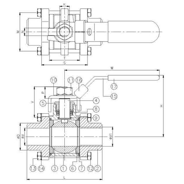
Standard
| Applicable standard | |
|---|---|
| Test and inspection | API 598 |
Materials
| Item | Part | Material | |
|---|---|---|---|
| 1 | Body | ASTM A351-CF8M / 1.4408 | ASTM A216-WCB / 1.0619 |
| 2 | Cap | ||
| 3 | Ball | ASTM A351-CF8M | |
| 4 | Stem | ASTM A276-316 | |
| 5 | Gland nut | AISI 304 | |
| 6 | Ball seat | PTFE / RTFE/CTFE | |
| 7 | Body seal | PTFE | |
| 8 | Stem packing | ||
| 9 | Thrust washer | ||
| 10 | Spring washer | AISI 304 | |
| 11 | Stem nut | ASTM A194 GR.8 | |
| 12 | Screw | ASTM A193-B8 | ASTM A193-B7 |
| 13 | Bolt nut | ASTM A193-B8 | ASTM A193-B7 |
| 14 | Spring washer | AISI 304 | |
| 15 | Handle | ASTM A167-304 | |
| 16 | Locking device | ||
| 17 | Handle sleeve | PVC | |
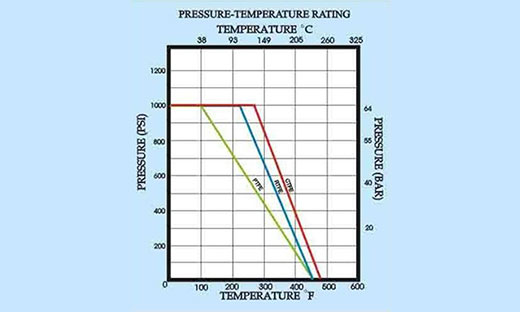
Pressure / temperature diagram
Dimensions – metric (mm)
| Pressure | DN | d | D | d1 | L | H | W | S |
|---|---|---|---|---|---|---|---|---|
| PN 63 | 8 | 8 | 13,5 | 12,7 | 64,5 | 54 | 102 | 35,5 |
| 10 | 12,7 | 17,5 | 12,7 | 64,5 | 54 | 102 | 35,5 | |
| 15 | 15 | 22 | 15 | 66 | 57 | 102 | 38 | |
| 20 | 20 | 27 | 20 | 83,5 | 66 | 120,5 | 43 | |
| 25 | 25 | 34 | 25 | 95 | 76 | 158,5 | 54 | |
| 32 | 32 | 42,5 | 32 | 111,2 | 81 | 158,5 | 65 | |
| 40 | 38 | 48,5 | 38 | 129,6 | 98 | 188 | 75 | |
| 50 | 50 | 61 | 50 | 151 | 106 | 188 | 88 | |
| 65 | 65 | 73 | 65 | 184 | 138 | 245 | 114 | |
| 80 | 80 | 90 | 80 | 209 | 154 | 245 | 132 | |
| 100 | 100 | 115 | 100 | 235 | 178 | 320 | 158 |
| Pressure | DN | T | M | N | V | P | K | Weight (kg) |
|---|---|---|---|---|---|---|---|---|
| PN 63 | 8 | 21,5 | 29 | 5 | 29,7 | 10,5 | 5/16″W | 0,41 |
| 10 | 21,5 | 29 | 5 | 29,7 | 10,5 | 5/16″W | 0,41 | |
| 15 | 24 | 33,2 | 5 | 30,1 | 10,5 | 5/16″W | 0,52 | |
| 20 | 28 | 37,5 | 6,5 | 36,5 | 13,5 | 3/8″W | 0,71 | |
| 25 | 35 | 42,4 | 8 | 40,6 | 15,5 | 7/16″W | 1,08 | |
| 32 | 45 | 50,9 | 8 | 41,8 | 15,5 | 7/16″W | 1,71 | |
| 40 | 55 | 59,4 | 9 | 48,5 | 17,5 | 1/2″W | 2,35 | |
| 50 | 66 | 73,4 | 9 | 49,4 | 17,5 | 1/2″W | 3,55 | |
| 65 | 86 | 96,5 | 12 | 72,1 | 33 | 3/4″W | 8,9 | |
| 80 | 100 | 81 | 12 | 65,6 | 33 | 3/4″W | 14,3 | |
| 100 | 125 | 102 | 16 | 76,2 | 39 | 1″W | 23,4 |
Dimensions – imperial (in)
| Pressure | NPS | d | D | d1 | L | H | W | S |
|---|---|---|---|---|---|---|---|---|
| 1000 W.O.G. | 1/4″ | 0,46 | 0,53 | 0,5 | 2,54 | 2,13 | 4,02 | 1,4 |
| 3/8″ | 0,50 | 0,69 | 0,5 | 2,54 | 2,13 | 4,02 | 1,4 | |
| 1/2″ | 0,59 | 0,87 | 0,59 | 2,6 | 2,24 | 4,02 | 1,5 | |
| 3/4″ | 0,79 | 1,06 | 0,79 | 3,29 | 2,6 | 4,74 | 1,69 | |
| 1″ | 0,98 | 1,34 | 0,98 | 3,74 | 2,99 | 6,24 | 2,13 | |
| 1-1/4″ | 1,26 | 1,67 | 1,26 | 4,38 | 3,19 | 6,24 | 2,56 | |
| 1-1/2″ | 1,5 | 1,91 | 1,5 | 5,11 | 3,66 | 7,4 | 2,95 | |
| 2″ | 1,97 | 2,4 | 1,97 | 5,94 | 4,17 | 7,4 | 3,46 | |
| 2-1/2″ | 2,56 | 2,87 | 2,56 | 7,24 | 5,43 | 9,65 | 4,49 | |
| 3″ | 3,15 | 3,54 | 3,15 | 8,23 | 6,06 | 9,65 | 5,2 | |
| 4″ | 3,94 | 4,53 | 3,94 | 9,25 | 7,01 | 12,6 | 6,22 |
| Pressure | NPS | T | M | N | V | P | K | Weight (lb) |
|---|---|---|---|---|---|---|---|---|
| 1000 W.O.G. | 1/4″ | 0,85 | 1,14 | 0,2 | 1,17 | 0,41 | 5/16″W | 0,90 |
| 3/8″ | 0,85 | 1,14 | 0,2 | 1,17 | 0,41 | 5/16″W | 0,90 | |
| 1/2″ | 0,94 | 1,31 | 0,2 | 1,19 | 0,41 | 5/16″W | 1,15 | |
| 3/4″ | 1,1 | 1,48 | 0,26 | 1,44 | 0,53 | 3/8″W | 1,57 | |
| 1″ | 1,38 | 1,67 | 0,31 | 1,6 | 0,61 | 7/16″W | 2,38 | |
| 1-1/4″ | 1,77 | 2 | 0,31 | 1,65 | 0,61 | 7/16″W | 3,77 | |
| 1-1/2″ | 2,17 | 2,34 | 0,35 | 1,91 | 0,69 | 1/2″W | 5,18 | |
| 2″ | 2,60 | 2,89 | 0,35 | 1,94 | 0,69 | 1/2″W | 7,83 | |
| 2-1/2″ | 3,39 | 3,8 | 0,47 | 2,84 | 1,3 | 3/4″W | 19,62 | |
| 3″ | 3,94 | 3,19 | 0,47 | 2,58 | 1,3 | 3/4″W | 31,53 | |
| 4″ | 4,92 | 4,02 | 0,63 | 3 | 1,54 | 1″W | 51,60 |
THREE-PIECE, WELDABLE, WITH PNEUMATIC ACTUATOR MOUNTING PAD
Features
- Butt-weld ends according to ANSI B16.25 and DIN 3239 part 1
- Investment casting
- Blow-out proof stem
- PTFE seat
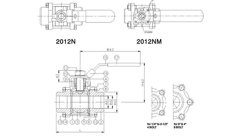
- ISO 5211 actuator mounting pad (2012NM)
Details – technical data
Standard
| Applicable standard | |
|---|---|
| Test and inspection | API 598 |
Materials
| Item | Part | Material | |
|---|---|---|---|
| 1 | Body | ASTM A351-CF8M / 1.4408 | |
| 2 | Cap | ||
| 3 | Ball | ||
| 4 | Stem | ASTM A276-316 | |
| 5 | Ball seat | PTFE | |
| 6 | Body seal | ||
| 7 | Stem packing | ||
| 8 | Thrust washer | ||
| 9 | Gland nut | AISI 304 | |
| 10 | Spring washer | ||
| 11 | Stem nut | ||
| 12 | Screw | ||
| 13 | Nut | ||
| 14 | Spring washer | ||
| 15 | Handle | ||
| 16 | Locking device | ||
| 17 | Handle sleeve | PVC | |
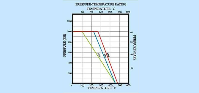
Pressure / temperature diagram
Dimensions – metric (mm)
| Pressure | DN | d1 | d2 | d3 | L | H | H1 |
|---|---|---|---|---|---|---|---|
| PN 63 | 8 | 11,6 | – | 14,7 | 65 | 58,5 | 18 |
| 10 | 12,5 | – | 18,1 | 65 | 58,5 | 18 | |
| 15 | 15 | 15,8 | 22,3 | 65 | 62 | 18,5 | |
| 20 | 20 | 20,9 | 27,7 | 75 | 62 | 22,5 | |
| 25 | 25 | 26,6 | 34,4 | 85 | 77 | 25 | |
| 32 | 32 | 35,1 | 43,2 | 101 | 82 | 26 | |
| 40 | 38 | 40,9 | 49,3 | 112 | 100 | 30 | |
| 50 | 50 | 52,5 | 61,5 | 130 | 108 | 30 | |
| 65 | 63 | 62,7 | 74,5 | 162 | 137 | 40 | |
| 80 | 76 | 77,9 | 91 | 188 | 145 | 40 | |
| 100 | 96 | 102 | 155,5 | 224 | 179 | 54 |
| Pressure | DN | W | M | D | ISO5211 | Torque (Nm) | Weight (kg) |
|---|---|---|---|---|---|---|---|
| PN 63 | 8 | 100 | 36 | M5 | FO3 | 3,5 | 0,35 |
| 10 | 100 | 36 | M5 | FO3 | 4 | 0,35 | |
| 15 | 100 | 36 | M5 | FO3 | 5,5 | 0,5 | |
| 20 | 125 | 36 | M5 | FO3 | 7,5 | 0,7 | |
| 25 | 149 | 42 | M5 | FO4 | 11 | 1 | |
| 32 | 149 | 42 | M5 | FO4 | 15 | 1,6 | |
| 40 | 190 | 50 | M6 | FO6 | 20 | 2,5 | |
| 50 | 190 | 50 | M6 | FO6 | 40 | 3,5 | |
| 65 | 250 | 70 | M8 | FO7 | 60 | 6,7 | |
| 80 | 250 | 70 | M8 | FO7 | 85 | 9,5 | |
| 100 | 323 | 102 | M12 | F10 | 150 | 19,1 |
Dimensions – imperial (in)
| Pressure | NPS | d1 | d2 | d3 | L | H | H1 |
|---|---|---|---|---|---|---|---|
| 1000 W.O.G. | 1/4″ | 0,46 | – | 0,58 | 2,56 | 2,3 | 0,71 |
| 3/8″ | 0,49 | – | 0,71 | 2,56 | 2,3 | 0,71 | |
| 1/2″ | 0,59 | 0,62 | 0,88 | 2,56 | 2,44 | 0,73 | |
| 3/4″ | 0,79 | 0,82 | 1,09 | 2,95 | 2,44 | 0,89 | |
| 1″ | 0,98 | 1,05 | 1,35 | 3,35 | 3,03 | 0,98 | |
| 1-1/4″ | 1,26 | 1,38 | 1,7 | 3,98 | 3,23 | 1,02 | |
| 1-1/2″ | 1,5 | 1,61 | 1,94 | 4,41 | 3,94 | 1,18 | |
| 2″ | 1,97 | 2,07 | 2,42 | 5,12 | 4,25 | 1,18 | |
| 2-1/2″ | 2,48 | 2,47 | 2,93 | 6,38 | 5,39 | 1,57 | |
| 3″ | 2,99 | 3,07 | 3,58 | 7,4 | 5,71 | 1,57 | |
| 4″ | 3,78 | 4,02 | 6,12 | 8,82 | 7,05 | 2,13 |
| Pressure | NPS | W | M | D | ISO5211 | Torque (in-lb) | Weight (lb) |
|---|---|---|---|---|---|---|---|
| 1000 W.O.G. | 1/4″ | 3,94 | 1,42 | M5 | FO3 | 31 | 0,77 |
| 3/8″ | 3,94 | 1,42 | M5 | FO3 | 35,4 | 0,77 | |
| 1/2″ | 3,94 | 1,42 | M5 | FO3 | 48,7 | 1,1 | |
| 3/4″ | 4,92 | 1,65 | M5 | FO3 | 66,4 | 1,54 | |
| 1″ | 5,87 | 1,65 | M5 | FO4 | 97,4 | 2,2 | |
| 1-1/4″ | 5,87 | 1,97 | M5 | FO4 | 132,8 | 3,53 | |
| 1-1/2″ | 7,48 | 1,97 | M6 | FO5 | 177 | 5,51 | |
| 2″ | 7,48 | 2,76 | M6 | FO5 | 354 | 7,72 | |
| 2-1/2″ | 9,84 | 2,76 | M8 | FO7 | 531 | 14,77 | |
| 3″ | 9,84 | 4,02 | M8 | FO7 | 752,3 | 20,94 | |
| 4″ | 12,72 | – | M12 | F10 | 1327,6 | 42,11 |
Related products
See related products from our range.